The Cement Mixer Structure
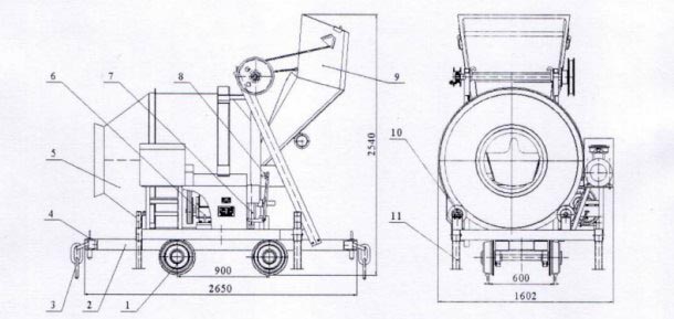
JZC500 series drum type cement mixer belongs to double-cone type mixing drum, which can be stirred and reversed. The self-falling cement mixer can mix plastic and semi-dry hard concrete. The mixing drum of this machine is rotated by the ring gear, which has reliable transmission and low noise. Low energy consumption, compact structure, stable operation, easy operation, good mixing quality and high productivity. The cement mixer is composed of a stirring mechanism, a feeding mechanism, a chassis. Figure 1
Mixing mechanism
The stirring mechanism is composed of a mixing drum, a supporting wheel and a rotating system.

Figure 1 Mixer structure diagram
1. Rail assembly 2, chassis assembly 3, three-ring chain 4, link pin 5, mixing drum 6, deceleration system 7, clutch 8, joystick 9, feed mechanism 10, idler 11, leg

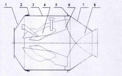
Figure 2 Mixing drum schematic
1, discharge blade 2, discharge cone 3, low blade 4, raceway, 4, high blade 5, roller 6, large ring gear 7, feed cone 8, discharge cone
The mixing drum (Fig. 2) is the working part of the cement mixer. The mixing barrel is double-conical. The barrel is welded with two pairs of high and low blades, which are arranged at an angle with the axis of the mixing drum. When the mixing drum rotates, the blades are in the material. While lifting the drop, the material is still moving back and forth in the axial direction, so the stirring motion is strong, and the homogenous concrete can be achieved by stirring for 35-45 seconds.

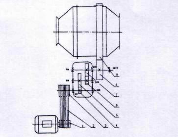
Figure 3 Rotating system diagram
1, motor pulley 2, V-belt 3, large pulley 4, primary pinion 5. Primary gear 6, secondary pinion 7, secondary large gear 8, output gear 9, large ring gear
Inside the discharge vertebral body of the mixing drum, a pair of discharge blades are welded to change the rotation direction of the mixing drum, and the concrete is pushed from the low blade to the discharge blade and discharged out of the cylinder.
The mixing drum is supported by four supporting rollers, which are rotated by the motor through the gearbox driving gear, so it is still reliable in foggy or rainy weather.
Rotating system (Fig. 3), the reduction gearbox is decelerated by the secondary cylindrical gear, and the forward and reverse rotation of the mixing cylinder is realized by the commutation of the motor.
2, feeding mechanism
The lifting and climbing operation of the feeding hopper is driven by the output shaft of the gear reduction gear through the steel wire strong reel of the feed clutch at the shaft end, and the clutch is controlled by the manual operating lever. The upper limit position of the hopper is automatically disengaged from the clutch by the limit device.
Driven by the clutch device, the wire rope climbs up along the loading rack rail through the pulley pulling hopper. When climbing to a certain height, a pair of rollers on the bottom of the hopper enters the horizontal rack of the loading rack, and the material is put into the mixing tank through the feeding funnel. .
3, chassis
The chassis is welded by channel steel, and two sets of rail wheels are installed below, and the ends of the rack are arranged.